

How To Draw A Node
| LaTeX |
|---|
Getting Started
Common Elements
Mechanics
Technical Text
Special Pages
Special Documents
Creating Graphics
Programming
Miscellaneous
Help and Recommendations
Appendices
|
| edit this box • edit the TOC |
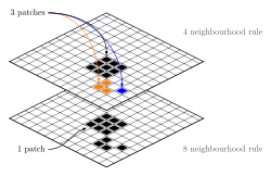
Example of graphics done with Tikz. Note the slightly translucent top layer.
One way to draw graphics directly with TeX commands is PGF/TikZ. TikZ can produce portable graphics in both PDF and PostScript formats using either plain (pdf)TEX, (pdf)Latex or ConTEXt. It comes with very good documentation and an extensive collection of examples: http://www.texample.net/tikz/
PGF ("portable graphics format") is the basic layer, providing a set of basic commands for producing graphics, and TikZ ("TikZ ist kein Zeichenprogramm" or "TikZ is not a Drawing program") is the frontend layer with a special syntax, making the use of PGF easier. TikZ commands are prevalently similar to Metafont, the option mechanism is similar to PsTricks syntax.
While the previous systems (picture, epic, pstricks or metapost) focus on the how to draw, TikZ focuses more on the what to draw. One could say that TikZ is to picture as LaTeX is to TeX. It's recommended to use it if your LaTeX distribution includes it.
Other packages building on top of TikZ (e.g., for drawing electrical circuits) can be found here: https://www.ctan.org/topic/pgf-tikz
In the following some basics of TikZ are presented.
Loading package, libraries - tikzpicture environment [edit | edit source]
Using TikZ in a LaTeX document requires loading the tikz package:
somewhere in the preamble. This will automatically load the pgf package. To load further libraries use
\usetikzlibrary {⟨list of libraries separated by commas⟩}
Examples for libraries are "arrows", "automata", "backgrounds", "calendar", "chains", "matrix", "mindmap", "patterns", "petri", "shadows", "shapes.geometric", "shapes.misc", "spy", "trees".
Drawing commands have to be enclosed in an tikzpicture environment
\begin {tikzpicture}[⟨options⟩] ⟨tikz commands⟩ \end {tikzpicture}
or alternatively
\tikz [⟨options⟩] {⟨tikz commands⟩}
One possible option useful for inlined graphics is
Without that option the lower end of the picture is put on the baseline of the surrounding text. Using this option, you can specify that the picture should be raised or lowered such that the height ⟨dimension⟩ is on the baseline.
Another option to scale the entire picture is
or different for height and width, e.g:
Specifying coordinates [edit | edit source]
Coordinates are specified in round brackets in an arbitrary TEX dimension either using Cartesian coordinates (comma separated), e.g. 1cm in the x direction and 2pt in the y direction
or using polar coordinates (colon separated), e.g. 1cm in 30 degree direction
Without specifying a unit (1,2), the standard one is cm (1cm,2cm). The positive x and y directions refer to right and up on a diagram respectively, and an increase in an angle is a counter-clockwise change, with 0 degrees pointing directly right.
Relative coordinates to the previous given point are given by adding one or two plus signs in front of the coordinate. With "++" the last point of the path becomes the current position, with "+" the previous point stays the current path position. Example: 2 standard units to the right of the last point used:
Syntax for paths [edit | edit source]
A path is a series of straight and curved line segments (in a simplified explanation). The instruction has to end with a semicolon.
\path [<options>]⟨specification⟩;
One instruction can spread over several lines, or several instructions can be put on one line.
Path actions [edit | edit source]
Options for path actions are e.g: "draw", "fill", "pattern", "shade" (a variation on filling that changes colors smoothly from one to another), "clip" (all subsequent drawings up to the end of the current scope are clipped against the current path and the size of subsequent paths will not be important for the picture size), "use as bounding box". The "\path" command with these options can be combined to: "\draw", "\fill", "\filldraw", "\pattern", "\shade", "\shadedraw", "\clip", "\useasboundingbox" .
Geometric path actions [edit | edit source]
Geometric path options: "rotate=<angle in degree>", "xshift=<length>", "yshift=<length>", "scale=<factor>", "xscale=<factor>", "yscale=<factor>".
Color [edit | edit source]
Color options for drawing paths: "color=<color name>", "draw=<line color>", "opacity=<factor>". Following colors are predefined: red, green, blue, cyan, magenta, yellow, black, gray, darkgray, lightgray, brown, lime, olive, orange, pink, purple, teal, violet and white.
Line width [edit | edit source]
Line width options: "line width=<dimension>", and abbreviations "ultra thin" for 0.1pt, "very thin" for 0.2pt, "thin" for 0.4pt (the default width), "semithick" for 0.6pt, "thick" for 0.8pt, "very thick" for 1.2pt, "ultra thick" for 1.6pt.
Line end [edit | edit source]
Line end, line join options: "line cap=<type: round, rect, or butt>", "arrows=<start arrow kind>-<end arrow kind>", "rounded corners", "rounded corners=<size>", "line join=<type: round, bevel, or miter>".
Line pattern [edit | edit source]
Line pattern options: "dash pattern=<dash pattern>" (e.g. "dash pattern=on 2pt off 3pt on 4pt off 4pt"), "dash phase=⟨dash phase⟩", "solid", "dashed", "dotted", "dashdotted", "densely dotted", "loosely dotted", "double".
Options for filling paths are e.g. "fill=<fill color>", "pattern=<name>", "pattern color=<color>"
Drawing straight lines [edit | edit source]
Straight lines are given by coordinates separated by a double minus,
\draw (1,0) -- (0,0) -- (0,1); | |
The first coordinate represents a move-to operation. This is followed by a series of "path extension operations", like "-- (coordinates)".
The same path with some drawing options:
\draw [red, dashed, very thick, rotate=30] (1,0) -- (0,0) -- (0,1); | |
A connected path can be closed using the "--cycle" operation:
\draw (1,0) -- (0,0) -- (0,1) -- cycle; | |
A further move-to operation in an existing path starts a new part of the path, which is not connected to the previous part of the path. Here: Move to (0,0) straight line to (2,0), move to (0,1) straight line to (2,1):
\draw (0,0) -- (2,0) (0,1) -- (2,1); | |
Two points can be connected by straight lines that are only horizontal and vertical. For a connection that is first horizontal and then vertical, use
| |
or first vertical then horizontal, use
| |
Drawing curved paths [edit | edit source]
Curved paths using a Bezier curve can be created using the "..controls() ..()" command, with one or two control points.
\draw (0,0) .. controls (1,1) .. (4,0) (5,0) .. controls (6,0) and (6,1) .. (5,2); | |

User-defined paths [edit | edit source]
User-defined paths can be created using the "to" operation. Without an option it corresponds to a straight line, exactly like the double minus command. Using the "out" and "in" option a curved path can be created. E.g. "[out=135,in=45]" causes the path to leave at an angle of 135 degree at the first coordinate and arrive at an angle of 45 degree at the second coordinate.
\draw (0,0) to (3,2); \draw (0,0) to[out=90,in=180] (3,2); \draw (0,0) to[bend right] (3,2); | |

(The syntax for a bend to the right may seem a little counter-intuitive. Think of it as an instruction to veer to the right at the beginning of the path and then smoothly curve to the end point, not as saying that the path curves to the right throughout its length.)
For rectangles a special syntax exists. Use a move-to operation to one corner and after "rectangle" the coordinates of the diagonal corner. The last one becomes the new current point.
\draw (0,0) rectangle (1,1); \shade [top color=yellow, bottom color=black] (0,0) rectangle (2,-1); \filldraw [fill=green!20!white, draw=green!40!black] (0,0) rectangle (2,1); | |

The fill color "green!20!white" means 20% green and 80% white mixed together.
Circles, ellipses [edit | edit source]
Circles and ellipses paths are defined beginning with their center then using the "circle command" either with one length as radius of a circle or with two lengths as semi-axes of an ellipse.
\draw (0,0) circle [radius=1.5]; \draw (0,0) circle (2cm); % old syntax with round brackets instead of square brackets \draw (0,0) circle [x radius=1.5cm, y radius=10mm]; \draw (0,0) circle (1.2cm and 8mm); % old syntax \draw (0,0) circle [x radius=1cm, y radius=5mm, rotate=30]; \draw [rotate=30] (0,0) ellipse (20pt and 10pt); % old syntax | |

Arcs [edit | edit source]
The command "arc" creates a part of a circle or an ellipse:
\draw (0,0) arc (0:270:8mm); \draw (0,0) arc (0:315:1.75cm and 1cm); \filldraw [fill=cyan, draw=blue] (0,0) -- (12mm,0mm) arc (0:30:12mm) -- (0,0); | |

Or in an alternative syntax:
\draw (0,0) arc[radius = 8mm, start angle= 0, end angle= 270]; \draw (0,0) arc[x radius = 1.75cm, y radius = 1cm, start angle= 0, end angle= 315];
Special curves [edit | edit source]
There are many more predefined commands for special paths, like "grid", "parabola", "sin", "cos" (sine or cosine curve in the interval [0,π/2]).
\draw [help lines] (0,0) grid (2,3); \draw [step=0.5, gray, very thin] (-1.4,-1.4) grid (1.4,1.4); \draw (0,0) parabola (1,1.5) parabola[bend at end] (2,0); \draw (0,0) sin (1,1) cos (2,0) sin (3,-1) cos (4,0) sin (5,1); | |

The option "help lines" denotes "fine gray".
To add arrow tips there are simple options for the drawing command:
\draw [->] (0,0) -- (30:20pt); \draw [<->] (1,0) arc (180:30:10pt); \draw [<<->] (2,0) -- ++(0.5,10pt) -- ++(0.5,-10pt) -- ++(0.5,10pt); | |
A loop can be realized by "\foreach ⟨variable⟩ in {⟨list of values⟩} ⟨commands⟩".
\foreach \x in {0,...,9} \draw (\x,0) circle (0.4); | |
PGF also has a math engine which enables you to plot functions:
\draw [domain=xmin:xmax] plot (\x, {function});
Many functions are possible, including factorial(\x), sqrt(\x), pow(\x,y), exp(\x), ln(\x), log10(\x), log2(\x), abs(\x), mod(\x,y), round(\x), floor(\x), ceil(\x), sin(\x), cos(\x), tan(\x), min(\x,y,), and max(\x,y). The trigonometric functions assume that x is in degrees; to express x in radians follow it with the notation "r", e.g., sin(\x r). Two useful constants are e, which is equal to 2.718281828, and pi, which is equal to 3.141592654.
An example with two functions:
\draw [help lines] (-2,0) grid (2,4); \draw [->] (-2.2,0) -- (2.2,0); \draw [->] (0,0) -- (0,4.2); \draw [green, thick, domain=-2:2] plot (\x, {4-\x*\x }); \draw [domain=-2:2, samples=50] plot (\x, {1+cos(pi*\x r)}); | |

Nodes [edit | edit source]
A node is typically a rectangle or circle or another simple shape with some text on it. In the simplest case, a node is just some text that is placed at some coordinate. Nodes are not part of the path itself, they are added to the picture after the path has been drawn.
Inside a path operation use the following syntax after a given coordinate:
node[<options>](<name>){<text>}
The "(<name>)" is a name for later reference and it is optional. If you only want to name a certain position without writing text there are two possibilities:
node[<options>](<name>){} coordinate[<options>](<name>) Writing text along a given path using the node command is shown as a simple example:
\draw [dotted] (0,0) node {1st node} -- (1,1) node {2nd node} -- (0,2) node {3rd node} -- cycle; | |

Possible options for the node command are e.g. "inner sep=<dimension>", "outer sep=<dimension>", "minimum size=<dimension>", "shape aspect=<aspect ratio>", "text=<color>", "font= ", "align=<left_right_center>".
A node is centered at the current coordinate by default. Often it would be better to have the node placed beside the actual coordinate: Right ("right" or "anchor=west"), left ("left" or "anchor=east"), above ("above" or "anchor=south"), below ("below" or "anchor=north"). Combinations are also possible, like "anchor=north east" or "below left".
To place nodes on a line or a curve use the " There exist some abbreviations: " The " Since nodes are often the only path operation on paths, there are special commands for creating paths containing only a node, the first with text ouput, the second without: One can connect nodes using the nodes' labels as coordinates. Having " Equivalent to Multiline text can be included inside a node. A new line is indicated by double backslash "\\", but additionally you have to specify the alignment using the node option "align=". Here an example: Once the node x has been defined, you can use anchors as defined above relative to (x) as "
\fill [fill=yellow] (0,0) node {1st node} -- (1,1) node[circle,inner sep=0pt,draw] {2nd node} -- (0,2) node[fill=red!20,draw,double,rounded corners] {3rd node};

pos=<fraction>" option, where fraction is a floating point number between 0 representing the previous coordinate and 1 representing the current coordinate.
\draw (0,0) -- (3,1) node[pos=0]{0} node[pos=0.5]{1/2} node[pos=0.9]{9/10};
![]()
at start" for "pos=0", "very near start" for "pos=0.125", "near start" for "pos=0.25", "midway" for "pos=0.5", "near end" for "pos=0.75", "very near end" for "pos=0.875", "at end" for "pos=1". sloped" option causes the node to be rotated to become a tangent to the curve. \node [<options>](<name>) at (<coordinate>){<text>}; \coordinate [<options>](<name>) at (<coordinate>);
\path(0,0) node(x) {} (3,1) node(y) {};" defined, the node at (0,0) got the name "(x)" and the one at (3,1) got the name "(y)".
\path (0,0) node(x) {} (3,1) node(y) {}; \draw (x) -- (y);
![]()
\coordinate (x) at (0,0); \coordinate (y) at (3,1); \draw (x) -- (y);
\filldraw (0,0) circle (2pt) node[align=left, below] {test 1\\is aligned left} -- (4,0) circle (2pt) node[align=center, below] {test 2\\is centered} -- (8,0) circle (2pt) node[align=right, below] {test 3\\is right aligned};
![]()
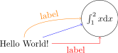
Path construction operations try to be clever, such that the path starts at the border of the node's shape and not from the node's center.
\path (0,0) node(x) {Hello World!} (3,1) node[circle,draw](y) { $ \int _ 1 ^ 2 x \mathrm d x $ }; \draw [->,blue] (x) -- (y); \draw [->,red] (x) -| node[near start,below] {label} (y); \draw [->,orange] (x) .. controls +(up:1cm) and +(left:1cm) .. node[above,sloped] {label} (y);
(x.<anchor>)", like "(x.north)". Examples [edit | edit source]
Example 1 [edit | edit source]
\documentclass {article} \usepackage {tikz} \begin {document} \begin {tikzpicture} \draw [thick,rounded corners=8pt] (0,0) -- (0,2) -- (1,3.25) -- (2,2) -- (2,0) -- (0,2) -- (2,2) -- (0,0) -- (2,0); \end {tikzpicture} \end {document}

Example 2 [edit | edit source]
\documentclass {article} \usepackage {tikz} \begin {document} \begin {tikzpicture}[scale=3] \draw [step=.5cm, gray, very thin] (-1.2,-1.2) grid (1.2,1.2); \filldraw [fill=green!20,draw=green!50!black] (0,0) -- (3mm,0mm) arc (0:30:3mm) -- cycle; \draw [->] (-1.25,0) -- (1.25,0) coordinate (x axis); \draw [->] (0,-1.25) -- (0,1.25) coordinate (y axis); \draw (0,0) circle (1cm); \draw [very thick,red] (30:1cm) -- node[left,fill=white] { $ \sin \alpha $ } (30:1cm |- x axis); \draw [very thick,blue] (30:1cm |- x axis) -- node[below=2pt,fill=white] { $ \cos \alpha $ } (0,0); \draw (0,0) -- (30:1cm); \foreach \x/\xtext in {-1, -0.5/-\frac {1}{2}, 1} \draw (\x cm,1pt) -- (\x cm,-1pt) node[anchor=north,fill=white] { $ \xtext $ }; \foreach \y/\ytext in {-1, -0.5/-\frac {1}{2}, 0.5/\frac {1}{2}, 1} \draw (1pt,\y cm) -- (-1pt,\y cm) node[anchor=east,fill=white] { $ \ytext $ }; \end {tikzpicture} \end {document}

Example 3: A Torus [edit | edit source]
\documentclass {article} \usepackage {tikz} \begin {document} \begin {tikzpicture} \draw (-1,0) to[bend left] (1,0); \draw (-1.2,.1) to[bend right] (1.2,.1); \draw [rotate=0] (0,0) ellipse (100pt and 50pt); \end {tikzpicture} \end {document}

Example 4: Some functions [edit | edit source]
\documentclass {article} \usepackage {tikz} \begin {document} \begin {tikzpicture}[domain=0:4] \draw [very thin,color=gray] (-0.1,-1.1) grid (3.9,3.9); \draw [->] (-0.2,0) -- (4.2,0) node[right] { $ x $ }; \draw [->] (0,-1.2) -- (0,4.2) node[above] { $ f ( x ) $ }; \draw [color=red] plot (\x,\x) node[right] { $ f ( x ) = x $ }; \draw [color=blue] plot (\x,{sin(\x r)}) node[right] { $ f ( x ) = \sin x $ }; \draw [color=orange] plot (\x,{0.05*exp(\x)}) node[right] { $ f ( x ) = \frac { 1 }{ 20 } \mathrm e^x $ }; \end {tikzpicture} \end {document}

How To Draw A Node
Source: https://en.wikibooks.org/wiki/LaTeX/PGF/TikZ
Posted by: stewartfortalwyneho.blogspot.com
0 Response to "How To Draw A Node"
Post a Comment