

What Genre Of Architecture Does The Drawing Show?

An architectural drawing or architect's drawing is a technical drawing of a building (or building projection) that falls inside the definition of architecture. Architectural drawings are used past architects and others for a number of purposes: to develop a design thought into a coherent proposal, to communicate ideas and concepts, to convince clients of the claim of a design, to assist a building contractor to construct it based on design intent, as a record of the design and planned development, or to make a record of a building that already exists.
Architectural drawings are fabricated according to a gear up of conventions, which include particular views (floor plan, section etc.), sheet sizes, units of measurement and scales, notation and cantankerous referencing.
Historically, drawings were made in ink on paper or similar fabric, and any copies required had to be laboriously made past hand. The twentieth century saw a shift to drawing on tracing paper and then that mechanical copies could be run off efficiently. The development of the figurer had a major touch on the methods used to pattern and create technical drawings,[1] making transmission drawing almost obsolete, and opening upwardly new possibilities of grade using organic shapes and complex geometry. Today the vast majority of drawings are created using CAD software.[2]
Size and calibration [edit]

The size of drawings reflects the materials available and the size that is convenient to transport – rolled upwardly or folded, laid out on a table, or pinned upwardly on a wall. The drafting procedure may impose limitations on the size that is realistically workable. Sizes are determined by a consistent paper size system, according to local usage. Normally the largest paper size used in mod architectural practice is ISO A0 (841 mm × 1,189 mm or 33.ane in × 46.8 in) or in the USA Arch E (762 mm × 1,067 mm or thirty in × 42 in) or Large E size (915 mm × i,220 mm or 36 in × 48 in).[3]
Architectural drawings are drawn to calibration and so that relative sizes are correctly represented. The scale is called both to ensure the whole building will fit on the chosen sheet size and to bear witness the required amount of detail. On the calibration of i-eighth of an inch to one foot (1:96) or the metric equivalent of one to 100, walls are typically shown as simple outlines corresponding to the overall thickness. At a larger scale, half an inch to one foot (one:24) or the nearest common metric equivalent i to xx, the layers of different materials that make upward the wall construction are shown. Construction details are drawn to a larger scale, in some cases full size (1 to 1 calibration).
Scale drawings enable dimensions to exist "read" off the drawing, i.e. measured directly. Royal scales (anxiety and inches) are every bit readable using an ordinary ruler. On a ane-eighth inch to i-pes scale drawing, the one-eighth divisions on the ruler can exist read off every bit anxiety. Architects normally apply a scale ruler with dissimilar scales marked on each edge. A third method, used by builders in estimating, is to mensurate direct off the cartoon and multiply by the scale gene.
Dimensions can exist measured off drawings made on a stable medium such every bit vellum. All processes of reproduction introduce pocket-sized errors, especially now that different copying methods hateful that the aforementioned drawing may exist re-copied, or copies made in several different means. Consequently, dimensions need to be written ("figured") on the drawing. The disclaimer "Exercise not scale off dimensions" is normally inscribed on architects' drawings, to guard against errors arising in the copying process.
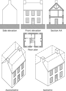
Standard views used in architects' drawings

Standard views used in architectural drawing [edit]
This section deals with the conventional views used to represent a building or structure. See the Types of architectural drawing department below for drawings classified according to their purpose.

Floor plan [edit]
A floor plan is the most cardinal architectural diagram, a view from above showing the arrangement of spaces in a edifice in the same way equally a map, simply showing the organization at a particular level of a edifice. Technically information technology is a horizontal department cut through a building (conventionally at four feet / ane metre and twenty centimetres in a higher place floor level), showing walls, windows and door openings, and other features at that level. The plan view includes anything that could be seen below that level: the flooring, stairs (simply just upwards to the programme level), fittings, and sometimes piece of furniture. Objects above the plan level (e.chiliad. beams overhead) can be indicated as dashed lines.
Geometrically, plan view is divers as a vertical orthographic project of an object onto a horizontal plane, with the horizontal plane cutting through the building.
Site plan [edit]
A site plan is a specific type of plan, showing the whole context of a building or group of buildings. A site program shows property boundaries and ways of admission to the site, and nearby structures if they are relevant to the design. For a development on an urban site, the site plan may need to prove adjoining streets to demonstrate how the design fits into the urban fabric. Inside the site boundary, the site plan gives an overview of the entire scope of piece of work. It shows the buildings (if any) already existing and those that are proposed, normally as a building footprint; roads, parking lots, footpaths, hard landscaping, trees, and planting. For a construction project, the site plan besides needs to show all the services connections: drainage and sewer lines, water supply, electrical and communications cables, exterior lighting etc.
Site plans are commonly used to stand for a building proposal prior to detailed pattern: cartoon up a site program is a tool for deciding both the site layout and the size and orientation of proposed new buildings. A site programme is used to verify that a proposal complies with local development codes, including restrictions on historical sites. In this context the site plan forms part of a legal agreement, and there may exist a requirement for information technology to be drawn up past a licensed professional: architect, engineer, landscape architect or land surveyor.[iv]

Elevation [edit]
An peak is a view of a building seen from one side, a flat representation of one façade. This is the most common view used to describe the external appearance of a edifice. Each elevation is labelled in relation to the compass direction it faces, e.g. looking toward the northward you would be seeing the southern elevation of the building.[5] Buildings are rarely a unproblematic rectangular shape in plan, so a typical summit may show all the parts of the building that are seen from a item direction.
Geometrically, an elevation is a horizontal orthographic projection of a building onto a vertical plane, the vertical plane normally being parallel to one side of the edifice.
Architects also use the give-and-take superlative as a synonym for façade, so the "north pinnacle" is the north-facing wall of the building.

Cantankerous section [edit]
A cross section, also simply called a section, represents a vertical plane cut through the object, in the same way as a floor plan is a horizontal department viewed from the tiptop. In the section view, everything cut by the department plane is shown every bit a bold line, often with a solid fill to show objects that are cut through, and anything seen beyond generally shown in a thinner line. Sections are used to depict the human relationship betwixt different levels of a edifice. In the Observatorium drawing illustrated here, the section shows the dome which tin be seen from the outside, a second dome that can only be seen inside the building, and the fashion the space between the 2 accommodates a large astronomical telescope: relationships that would be difficult to understand from plans lone.
A exclusive pinnacle is a combination of a cantankerous department, with elevations of other parts of the building seen beyond the section plane.
Geometrically, a cross section is a horizontal orthographic projection of a building on to a vertical plane, with the vertical aeroplane cutting through the building.
Isometric and axonometric projections [edit]
Isometric and axonometric projections are a simple way of representing a three dimensional object, keeping the elements to scale and showing the relationship between several sides of the same object, and then that the complexities of a shape tin exist conspicuously understood.
There is some confusion over the distinction between the terms isometric and axonometric. "Axonometric is a give-and-take that has been used by architects for hundreds of years. Engineers utilize the discussion axonometric every bit a generic term to include isometric, diametric and trimetric drawings."[half-dozen] This article uses the terms in the architecture-specific sense.
Despite fairly complex geometrical explanations, for the purposes of practical drafting the difference between isometric and axonometric is simple (meet diagram above). In both, the programme is drawn on a skewed or rotated grid, and the verticals are projected vertically on the folio. All lines are drawn to scale so that relationships between elements are accurate. In many cases a dissimilar calibration is required for different axes, and again this can be calculated but in do was often just estimated past eye.
- An isometric uses a plan grid at 30 degrees from the horizontal in both directions, which distorts the plan shape. Isometric graph paper can be used to construct this kind of cartoon. This view is useful to explain construction details (e.g. iii dimensional joints in joinery). The isometric was the standard view until the mid twentieth century, remaining pop until the 1970s, especially for textbook diagrams and illustrations.[7] [eight]
- Cabinet projection is similar, simply merely one axis is skewed, the others being horizontal and vertical. Originally used in cabinet making, the advantage is that a principal side (e.g. a cabinet forepart) is displayed without distortion, so but the less important sides are skewed. The lines leading away from the middle are drawn at a reduced scale to lessen the caste of distortion. The cabinet projection is seen in Victorian engraved advertisements and architectural textbooks,[seven] merely has near disappeared from general use.
- An axonometric uses a 45-degree plan grid, which keeps the original orthogonal geometry of the plan. The great advantage of this view for compages is that the draftsman can work directly from a programme, without having to reconstruct it on a skewed grid. In theory the programme should exist fix at 45 degrees, but this introduces disruptive coincidences where opposite corners align. Unwanted effects can be avoided by rotating the plan while still projecting vertically. This is sometimes called a planometric or plan oblique view,[ix] and allows freedom to choose whatever suitable angle to present the most useful view of an object.
Traditional drafting techniques used thirty–60 and 45 degree set up squares, and that determined the angles used in these views. In one case the adjustable square became mutual those limitations were lifted.
The axonometric gained in popularity in the twentieth century, not simply as a convenient diagram only as a formal presentation technique, adopted in particular past the Modern Movement.[six] Axonometric drawings feature prominently in the influential 1970's drawings of Michael Graves, James Stirling and others, using not only straightforward views but worms-eye view, unusually and exaggerated rotations of the plan, and exploded elements.[10]
The axonometric view is not readily generated by CAD programmes which create views from a three dimensional model. Consequently, information technology is now rarely used.
Detail drawings [edit]
Detail drawings show a pocket-size part of the structure at a larger scale, to show how the component parts fit together. They are as well used to bear witness modest surface details, for instance decorative elements. Section drawings at large scale are a standard way of showing building construction details, typically showing complex junctions (such as floor to wall junction, window openings, eaves and roof apex) that cannot be clearly shown on a drawing that includes the full height of the building. A full fix of structure details needs to testify plan details also as vertical section details. One detail is seldom produced in isolation: a gear up of details shows the information needed to understand the structure in three dimensions. Typical scales for details are 1/x, ane/five and full size.
In traditional construction, many details were then fully standardized, that few detail drawings were required to construct a building. For example, the construction of a sash window would be left to the carpenter, who would fully empathize what was required, but unique decorative details of the façade would be fatigued up in detail. In dissimilarity, modern buildings need to be fully detailed considering of the proliferation of unlike products, methods and possible solutions.
Architectural perspective [edit]

Perspective in the way of the classic Ideal city past Jean-Max Albert,1977.

Two point perspective, interior of Dercy House by Robert Adam, 1777.
Perspective in drawing is an approximate representation on a flat surface of an image equally it is perceived past the middle. The key concepts hither are:
- Perspective is the view from a particular stock-still viewpoint.
- Horizontal and vertical edges in the object are represented by horizontals and verticals in the drawing.
- Lines leading away into the distance appear to converge at a vanishing point.
- All horizontals converge to a point on the horizon, which is a horizontal line at heart level.
- Verticals converge to a point either to a higher place or below the horizon.
The bones categorization of artificial perspective is by the number of vanishing points:
- One-indicate perspective where objects facing the viewer are orthogonal, and receding lines converge to a single vanishing signal.
- 2-point perspective reduces distortion by viewing objects at an bending, with all the horizontal lines receding to one of ii vanishing points, both located on the horizon.
- Three-bespeak perspective introduces boosted realism past making the verticals recede to a 3rd vanishing betoken, which is above or below depending upon whether the view is seen from to a higher place or below.
The normal convention in architectural perspective is to use two-betoken perspective, with all the verticals drawn equally verticals on the page.
Iii-signal perspective gives a casual, photographic snapshot result. In professional architectural photography, conversely, a view camera or a perspective control lens is used to eliminate the third vanishing bespeak, and so that all the verticals are vertical on the photograph, as with the perspective convention. This can also be done past digital manipulation of a photo taken with a standard lens.
Aerial perspective is a technique in painting, for indicating altitude by approximating the effect of the atmosphere on distant objects. In daylight, as an ordinary object gets further from the centre, its dissimilarity with the background is reduced, its color saturation is reduced, and its colour becomes more blue. Not to be confused with aerial view or bird'due south eye view, which is the view as seen (or imagined) from a loftier vantage bespeak. In J M Gandy'south perspective of the Bank of England (see analogy at the offset of this article), Gandy portrayed the edifice as a picturesque ruin in order to show the internal plan arrangement, a forerunner of the cutaway view.[xi]
A montage epitome is produced by superimposing a perspective epitome of a edifice on to a photographic groundwork. Intendance is needed to record the position from which the photograph was taken, and to generate the perspective using the same viewpoint. This technique is popular in estimator visualization, where the building can be photorealistically rendered, and the concluding image is intended to be most indistinguishable from a photograph.
Sketches and diagrams [edit]
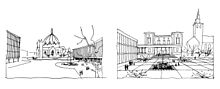
Builder's early concept sketches.
A sketch is a rapidly executed freehand drawing, a quick fashion to record and develop an idea, not intended every bit a finished piece of work. A diagram could too be drawn freehand only deals with symbols, to develop the logic of a blueprint. Both can be worked upwardly into a more presentable course and used to communicate the principles of a design.[ citation needed ]
In architecture, the finished work is expensive and time consuming, so information technology is important to resolve the design as fully as possible before structure work begins. Complex mod buildings involve a large squad of different specialist disciplines, and communication at the early design stages is essential to keep the design moving towards a coordinated outcome.[12] Architects (and other designers) get-go investigating a new design with sketches and diagrams, to develop a rough pattern that provides an adequate response to the detail pattern problems.
At that place are two basic elements to a building pattern, the aesthetic and the practical. The aesthetic element includes the layout and visual appearance, the anticipated feel of the materials, and cultural references that will influence the way people perceive the edifice. Practical concerns include space allocated for different activities, how people enter and move around the building, daylight and bogus lighting, acoustics, traffic dissonance, legal matters and edifice codes, and many other problems. While both aspects are partly a matter of customary practise, every site is unlike. Many architects actively seek innovation, thereby increasing the number of problems to exist resolved.
Architectural legend often refers to designs made on the dorsum of an envelope or on a napkin.[xiii] Initial thoughts are important, even if they take to be discarded forth the manner, because they provide the central thought effectually which the blueprint tin develop.[xiv] Although a sketch is inaccurate, it is disposable and allows for freedom of thought, for trying different ideas apace. Selection becomes sharply reduced once the blueprint is committed to a scale drawing, and the sketch stage is almost always essential.
Diagrams are mainly used to resolve applied matters. In the early on phases of the design architects use diagrams to develop, explore, and communicate ideas and solutions. They are essential tools for thinking, trouble solving, and communication in the design disciplines. Diagrams can be used to resolve spatial relationships, but they tin can also represent forces and flows, e.g. the forces of sun and wind, or the flows of people and materials through a edifice.[15]
An exploded view diagram shows component parts dis-assembled in some way, so that each can be seen on its own. These views are common in technical manuals, but are too used in compages, either in conceptual diagrams or to illustrate technical details. In a cutaway view parts of the exterior are omitted to show the interior, or details of internal construction.[16] Although common in technical illustration, including many edifice products and systems, the cutaway is in fact fiddling-used in architectural drawing.
Types [edit]
Architectural drawings are produced for a specific purpose, and tin can exist classified accordingly. Several elements are frequently included on the same canvas, for example a sheet showing a plan together with the principal façade.
Presentation drawings [edit]
Drawings intended to explain a scheme and to promote its merits. Working drawings may include tones or hatches to emphasize dissimilar materials, but they are diagrams, not intended to appear realistic. Basic presentation drawings typically include people, vehicles and trees, taken from a library of such images, and are otherwise very like in fashion to working drawings. Rendering is the art of adding surface textures and shadows to show the visual qualities of a building more realistically. An architectural illustrator or graphic designer may be employed to prepare specialist presentation images, usually perspectives or highly finished site plans, floor plans and elevations etc.
Survey drawings [edit]
Measured drawings of existing land, structures and buildings. Architects need an accurate set of survey drawings equally a basis for their working drawings, to plant exact dimensions for the structure work. Surveys are unremarkably measured and drawn up by specialist country surveyors.
Record drawings [edit]
Historically, architects have made record drawings in gild to understand and emulate the smashing architecture known to them. In the Renaissance, architects from all over Europe studied and recorded the remains of the Roman and Greek civilizations, and used these influences to develop the architecture of the menstruum. Records are made both individually, for local purposes, and on a large scale for publication. Celebrated surveys worth referring to include:
- Colen Campbell's Vitruvius Brittanicus, illustrations of English language buildings by Inigo Jones and Sir Christopher Wren, as well as Campbell himself and other prominent architects of the era.
- The Survey of London, founded in 1894 by Charles Robert Ashbee and now available through English Heritage. A record of notable streets and individual buildings in the former Canton of London.
- Historic American Buildings Survey, records of notable buildings fatigued up during the 1930s Depression, this collection is held by the Library of Congress and is available copyright-costless on the internet.
Record drawings are also used in construction projects, where "as-built" atmospheric condition of the completed building are documented to take account of all the variations made during the grade of construction.
Working drawings [edit]
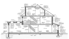

Detailed Parapet Wall Cartoon
A comprehensive set of drawings used in a building structure project: these volition include non only architect's drawings, but structural and other engineering drawings as well. Working drawings logically subdivide into location, assembly and component drawings.[9]
- Location drawings, also called general arrangement drawings, include flooring plans, sections and elevations: they show where the structure elements are located.
- Assembly drawings show how the unlike parts are put together. For example, a wall detail will testify the layers that brand upwards the construction, how they are stock-still to structural elements, how to terminate the edges of openings, and how prefabricated components are to be fitted.
- Component drawings enable self-contained elements e.thou. windows and doorsets, to be fabricated in a workshop, and delivered to site consummate and prepare for installation. Larger components may include roof trusses, cladding panels, cupboards and kitchens. Complete rooms, especially hotel bedrooms and bathrooms, may be made every bit prefabricated pods complete with internal decorations and fittings.
Formerly, working drawings would typically combine plans, sections, elevations and some details to provide a complete explanation of a edifice on ane canvas. That was possible because picayune particular was included, the building techniques involved being mutual knowledge amid building professionals. Modern working drawings are much more detailed and it is standard practice to isolate select areas of the projection on dissever sheets. Notes included on drawings are brief, referring to standardized specification documents for more information. Understanding the layout and structure of a modern building involves studying an often-sizeable prepare of drawings and documents.
Drafting [edit]

Architect at his drawing board (1893).
Until the latter office of the 20th century, all architectural drawings were manually produced, if not by the architects, then past trained (merely less skilled) draftsmen (or drafters), who did not generate the design, merely did make many of the less important decisions. This system has continued with CAD drafting: many blueprint architects have little or no knowledge of CAD software programmes, relying upon others to take their designs beyond the sketch stage. Draftsmen often specialize in a type of structure, such as residential or commercial, or in a type of construction: timber frame, reinforced concrete, prefabrication, etc.[17]
The traditional tools of the architect were the drawing board or drafting tabular array, T-square and set squares, protractor, compasses, pencil, and cartoon pens of unlike types.[fourteen] Drawings were fabricated on vellum, coated linen, and tracing paper. Lettering would either be done by mitt, mechanically using a stencil, or a combination of the two. Ink lines were drawn with a ruling pen, a relatively sophisticated device similar to a dip-in pen, but with adjustable line width, capable of producing a very fine controlled line width. Ink pens had to be dipped into ink often. Draftsmen worked standing up, keeping the ink on a separate table to avoid spilling ink on the drawing.[ citation needed ]
Developments in the 20th century included the parallel motion drawing board, every bit well as more circuitous improvements on the basic T-square. The development of reliable technical drawing pens allowed for faster drafting and stenciled lettering. Letraset dry transfer lettering and half-tone sheets were pop from the 1970s until[ when? ] computers made those processes obsolete.[ citation needed ]
CGI and computer-aided design [edit]

Figurer generated perspective of the Moscow School of Direction, by David Adjaye.
Reckoner-aided blueprint (more often than not referred to by the acronym CAD) is the use of computer software to create drawings. Today the vast bulk of technical drawings of all kinds are made using CAD. Instead of drawing lines on paper, the computer records equivalent data electronically. There are many advantages to this system: repetition is reduced because complex elements can exist copied, duplicated and stored for re-use. Errors tin be deleted, and the speed of drafting allows many permutations to be tried earlier the pattern is finalized. On the other hand, CAD drawing encourages a proliferation of detail and increased expectations of accurateness, aspects which reduce the efficiency originally expected from the motion to computerization.[ citation needed ]

An example of a drawing drafted in AutoCAD
Professional CAD software such as AutoCAD is circuitous and requires both training and feel before the operator becomes fully productive. Consequently, skilled CAD operators are oft divorced from the design procedure. Simpler software such as SketchUp and Vectorworks allows for more intuitive drawing and is intended as a design tool.[xviii] [xix]
CAD is used to create all kinds of drawings, from working drawings to photorealistic perspective views. Architectural renderings (besides called visualizations) are made by creating a three-dimensional model using CAD. The model can exist viewed from any direction to observe the well-nigh useful viewpoints. Different software (for example Autodesk 3ds Max) is and so used to utilise color and texture to surfaces, and to represent shadows and reflections. The result tin be accurately combined with photographic elements: people, cars, groundwork landscape.[ citation needed ]
Edifice Information Modeling [edit]
Building data modeling (BIM) is the logical development of CAD drawing, a relatively new technology just fast becoming mainstream. The design team collaborates to create a 3-dimensional computer model, and all plans and other ii-dimensional views are generated directly from the model, ensuring spatial consistency. The key innovation hither is to share the model via the internet, so that all the design functions (site survey, compages, structure and services) tin can be integrated into a unmarried model, or as a series of models associated with each specialism that are shared throughout the design development procedure. Some form of management, not necessarily by the builder, needs to be in identify to resolve conflicting priorities. The starting point of BIM is spatial design, just it likewise enables components to be quantified and scheduled straight from the information embedded in the model.[ citation needed ]. Building information modelling can exist characterized into three different levels ranging from 0-3. These levels represent BIM maturity and distinguishes the amount of cooperation in projects. They gauge information being shared throughout the whole process.
Level 0 is individualized with no collaboration. Individuals are working on their own CAD files separately and working using their ain standards. These are known to be more than traditional ways which are being phased out therefore no longer being used today.
Level 1 is a mixture of 3D and 2D work. Project teams are required to manage and share information amongst the squad. Aspects such equally "naming conventions" should be adopted.
Level two involves all team members using 3D models. Although they might non being using the same data, the built environment is shared through a similar file formats. This level as well introduces construction sequencing and cost.
Level 3 involves working on a shared project model. The model exists in a central environment and can be modified by everyone. Conflicting information is reduced due to existent time update on models. Subsequently levels include sequencing components, cost estimation and accounting for upfront costs.
Parametric Blueprint [edit]
Parametric pattern is an instance of calculator intelligence rising in the field of architecture. Information technology is the creation of complex relationships between models. Measurements in parametric pattern connect by scripts. Users can adjust and suit their models based on measurements. Changing one measurement will affect other measurements based on the set parameters. The parametric pattern uses scalability and adjustments which involve complex organic shapes. It allows for the cosmos of forms that would not be possible with regular 3d modeling or would take copious amounts of time. Models can decrease production time, therefore, allowing for the time allotted to other times of the design procedure. An statement with parametric pattern is the question of practicality. At times, it is unsure whether or non these styles properly comply with users wants and needs.[20] Real-life examples of parametric designs would exist The Metropol Parasol in Seville or the County in Guangzhou China. These forms accept a commonality with circuitous repetitive patterns which twist, bend and curve in dramatic means. These lattices are unique and in that location is a complexity tied with how they look. This is coined as "parametricism" by Zaha Hadid which is a style based on digital animation techniques.
Architectural animation [edit]

Example of real life parametric model
An architectural animation is a short pic showing how a proposed building will look: the moving image makes 3-dimensional forms much easier to sympathize. An animation is generated from a series of hundreds or even thousands of still images, each fabricated in the same way equally an architectural visualization. A computer-generated building is created using a CAD programs, and that is used to create more than or less realistic views from a sequence of viewpoints. The simplest animations utilise a moving viewpoint, while more than circuitous animations can include moving objects: people, vehicles, and so on.[ citation needed ]
Digital Era in Architecture [edit]
Schools are producing well versed architecture students who perform in computer assisted collaboration, construction automation and intelligent buildings which hope to have equally much affect before the adaptation of technologies. It's of import to sympathize that architects are problem solvers and critical thinking which has been used since the dawn of man is still existence carried on. The thought of innovation, responsiveness and disquisitional thinking will never be "phased out" and always relevant today. Although pure drafting, which involves manually drawing plans for construction, are not being used every bit often because of CAD, they are training architects to do human centered designer and to swoop deeper into the civilization to ultimately understand clientele . Homo centered blueprint involves the human perspective in all steps of the design procedure .The unpredictability and complexity of humans are unmatched with any pre-programmed systems.
Virtual Reality [edit]
Virtual reality in architectural projects helps designers understand spaces from a cognitive perspective.[21] VR stands for virtual reality and explains an experience in a world that doesn't exist. Virtual reality creates an feel generated by a computer program. The use of motion tracking allows for quick manipulation. It creates an individual secluded feel. Architecture firms are using this every bit a tool to allow employees to acquire and create a more engaging experience for both clients and employees. Benefits of VR for architecture include low start-upwards costs, gaining a competitive edge, avoiding revision, and the duplication of real-world scenarios. By placing a customer into the virtual globe, the feedback is frequently more than straight forward equally the client can walk through based on their needs and artful choices.
Online Practices [edit]
Due to COVID-19. architecture firms have increasingly shifted to a digital environment for collaboration. Video conferencing is proving to be a popular manner of meeting with clients and simulating the studio environment. Collaboration and advice using programs like Zoom are common consistently being used. Since the get-go of the epidemic, people are expected to be increasingly well versed with applied science. Although coordination is ofttimes hard, programs like BIM help improve workflow between both architects clients. However, relationships with clients are harder to facilitate considering clients are not able to touch or feel the work.[22] Adaptation is critical every bit more and more programs are beingness implemented among the studio to support staff.
.
Architectural reprographics [edit]
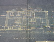
Reprographics or reprography covers a variety of technologies, media, and back up services used to make multiple copies of original drawings. Prints of architectural drawings are however sometimes called blueprints, afterwards one of the early on processes which produced a white line on blue paper. The process was superseded by the dye-line print system which prints black on white coated paper (Whiteprint). The standard modern processes are the ink-jet printer, light amplification by stimulated emission of radiation printer and photocopier, of which the ink-jet and light amplification by stimulated emission of radiation printers are ordinarily used for large-format press. Although colour printing is now commonplace, it remains expensive above A3 size, and architect'south working drawings withal tend to adhere to the black and white / greyscale aesthetic.
Run across besides [edit]
- Architectural model
- Copyright in architecture in the Us
- Cartoon
- Engineering drawing
- Layers in a standard architectural drawing
- Linear scale
- List of museums with major collections of European prints and drawings
- Museum for Architectural Drawing, Berlin, Germany
- Multiview orthographic projection
- Preservation: Library and Archival Science
- Structural cartoon
- Technical drawing
References [edit]
- ^ Gary R. Bertoline et al. (2002) Technical Graphics Communication. p.12.
- ^ Wisegeek, the basic definition of the scope of CAD drawings.
- ^ David Byrnes, AutoCAD 2008 For Dummies. Publisher: John Wiley & Sons; illustrated edition (4 May 2007). ISBN 0-470-11650-1
- ^ City of Ottawa, specific requirements for drawings to exist submitted for a building allow Archived January two, 2014, at the Wayback Machine. Local authorities worldwide publish like information.
- ^ Ching, Frank (1985), Architectural Graphics – Second Edition, New York: Van Norstrand Reinhold, ISBN0-442-21862-1
- ^ a b Alan Piper, Drawing for Designers. Laurence King Publishing 2007. ISBN 978-1-85669-533-half dozen Page 57, definition of axonometric drawing
- ^ a b W. B. McKay: McKay's Edifice Structure. Donhead Publishing 2005. ISBN 978-i-873394-72-4 A new reprint of the combined iii volumes that McKay published betwixt 1938 and 1944. Heavily illustrated textbook of architectural detailing.
- ^ Sample pages of isometric drawings from McKay'south Building Structure Archived July 10, 2011, at the Wayback Auto
- ^ a b Arthur Thompson, Architectural Pattern Procedures, Second Edition. Architectural Printing: Elsevier 2007. ISBN 978-0-340-71941-1
- ^ Thomas W Schaller, Architecture in Watercolour. Van Nostrand Re9inhold, New York 1990. ISBN 0-442-23484-8
- ^ The Peachy Perspectivists, by Gavin Stamp. RIBA Drawings Serial, published by Trefoil Books London 1982. ISBN 0-86294-002-8
- ^ Richard Boland and Fred Collopy (2004). Managing as designing. p.69.
- ^ https://www.theguardian.com/artanddesign/2009/mar/08/compages-exhibition%7CLe Corbusier's sketch blueprint for his Cabanon
- ^ a b Rendow Yee (2002). Architectural Drawing: A Visual Compendium of Types and Methods. second Edition. Wiley, 2002.
- ^ Ellen Yi-Luen Practise†& Marker D. Gross (2001). "Thinking with diagrams in architectural design". In: Artificial Intelligence Review 15: 135–149, 2001.
- ^ Andreas C. Papadakis (1988). Deconstruction in Architecture: In Architecture and Urbanism. p.65.
- ^ Bureau of Labor Statistics. Occupational Outlook Handbook, 2008–09 Edition: Drafters dated: 18 Dec 2007. accessed: 24 September 2008.
- ^ "The All-time 3D Architecture/ BIM Software (Many are Complimentary)". All3DP Pro. 2019-07-sixteen. Retrieved 2020-12-09 .
- ^ "Vectorworks 2021 Is Here! half-dozen Things BIM Users Volition Honey". www.engineering.com . Retrieved 2020-12-09 .
- ^ "What Is Parametric Design in Compages? How Is It Shaping the Industry?". Fusion 360 Blog. 2020-12-15. Retrieved 2021-04-13 .
- ^ LTD, TMD STUDIO (2020-02-01). "Virtual Reality Uses in Architecture and Design". Medium . Retrieved 2021-04-13 .
- ^ "How Architects Are Making It Work from Dwelling During COVID-xix". City. 2020-03-23. Retrieved 2021-04-13 .

Source: https://en.wikipedia.org/wiki/Architectural_drawing
Posted by: stewartfortalwyneho.blogspot.com
0 Response to "What Genre Of Architecture Does The Drawing Show?"
Post a Comment